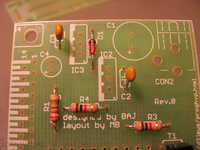
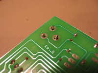
The THVP board solder side. Its a single-sided board, no jumper wires.
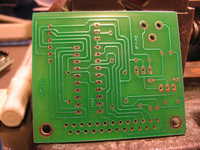
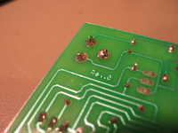
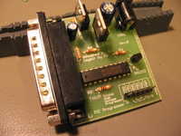
Top side of the THVP board. Note that to program PICs you need to either use "in-circuit programming" (aka ICSP in Microchip lingo), or a programming adapter. like the one described later.
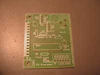
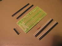
This is a programming adapter that allows to program a variety of PICs in a variety of sizes.
Its a single-sided board, one jumper wire is required.
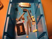
The required parts. Not shown are the cable to connect to the PC parallel port, the cable to connect the THVP board with the programming adapter, and the power supply.
Lets get started.
We are starting with the low profile parts. In this case, D1, a standard diode.
This is a 1N4148 diode, but most standard diodes with a forward voltage drop of approx 0.7V would work fine.
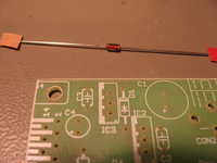
The diode is a polarized part. The cathode is marked with a band or ring.
The board's legend also shows that band.
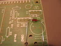
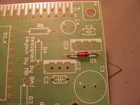
D1 inserted.
R1, a 270 Ohms resistor.
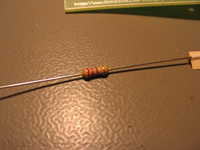
Resistors are not polarized, so you can insert them both ways.
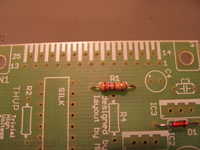
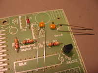
Resistors R2-R4, 1 kOhm.
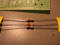
All three of them in place.
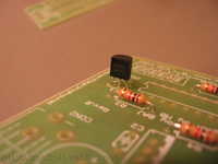
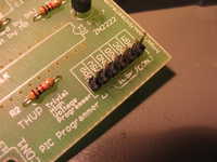
Next part: T1, a transistor. This is a BC547, a standard NPN transitor. Most NPN transistors will work here. For example a 2N2222.
Polarity does matter here. In this case, the center lead is the base pin, the one farthest away from the camera is the emitter, and the nearest is the collector.
Transistor in place.
Moving on to the capacitors, C2 and C3. These are 100nF ceramic capacitors. They are not polarized.
They are marked with "104".
And this is where they go.
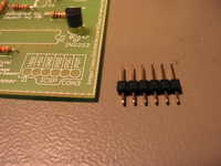
CON3, the ICSP programming connector. Its a 6pin header, .1" pitch. If you wanted, you could also solder a 6pin cable directly onto the board.
CON3 in place.
Now, the electrolytic capacitors, C1 and C4. Both are polarized. The negative terminal is marked with a white bar and a minus.
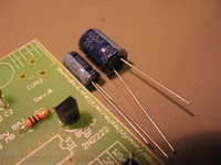
The smaller one, C4, is shown here. Please note the tiny "+" on the board's legend. It shows the positive side of the capacitor.
C4 is 1 uF.
The bigger one, C1, is valued 100uF. Again, a tiny "+" marks the positive side of the capacitor.
Important: A electrolytic capacitor can explode if inserted the wrong way.
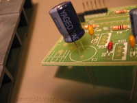
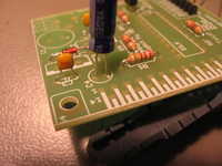
This is how it should look. Note the white bars on C1 and C4.
CON2 is the power supply connector. Its a barrel type and has a 2.5mm center pole. The center carries the positive ("+") voltage.
Connect only DC voltages to CON2, never AC. Voltage range is 15-21V.
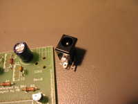
Due to the nature of the terminals on this connector, you have to squish them a little to fit the already large holes in the board.
This is how it should look.

And like this on the underside.
And when soldered...
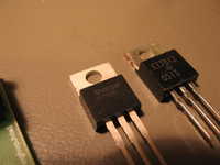
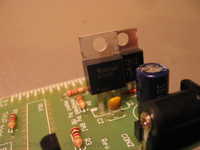
Next are the voltage regulators. We need two, IC2, a 5V linear regulator, and IC3, the same for 12V.
They are typically marked something like LM78xx (xx being the voltage, like 05, or 12) or uA78xx, some other prefix followed by 78xx.
First put IC3, the 7812, in place.
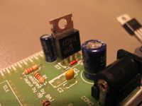
And then IC2, the 7805.
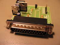
The biggest part on the board is next, the male SUB-D 25 parallel port connector, CON1. You can use a parallel port cable (SUB-D25 male to SUB-D25 female) of up to 2 meters (or 6ft).
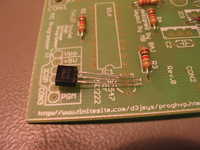
Last part is the buffer IC, IC1. Its a 74HCT573.
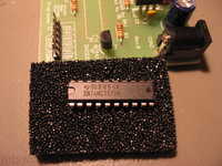
Make sure you get the orientation right, pin 1 is oriented towards T1.
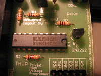
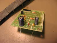
The finished THVP board.
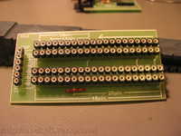
Now we move to the second board, the programming adapter board.
Here you see it with all the necessary parts.
Start with this jumper wire.
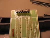
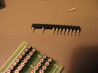
Next, CON1, the connector between this board and the THVP programmer. Other 0.1" pitch connectors would work here as well.
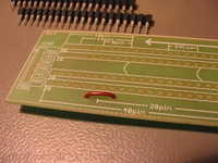
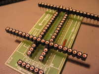
The sockets for the PICs should be carefully aligned. Start with the inner rows. Using an object with an exact 0.3" (300mil) spacing will greatly help, as I did with the other two rows in the photo.
Also make sure that the middle and the two ends are all level. Uneven sockets would make it hard to plug in a PIC with all pins firmly contacting.
Now solder one of the other rows. Again, make sure all pins are on one level.
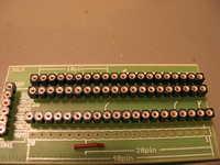
To help alignment, I again used a piece of these socket pin rows. In order to be able to plug it into the other rows, I had to remove some pins where the inner rows would have been in the way.
Align both ends, and the middle (soldering one pin of a row, each on one end, then the other, then the middle, greatly simplifies things here).
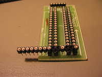
And we're done with this board :-)
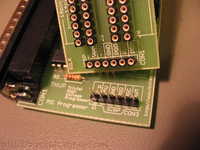
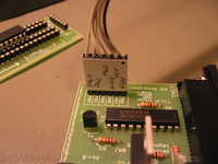
This shows the ICSP connectors of both boards, and how they match.
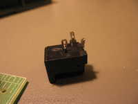
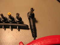
As already mentioned, you'll need a barrel type DC power jack with a 2.5mm diameter center pin. The power supply side looks like this.
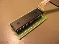
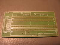
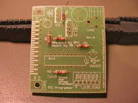
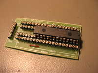
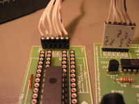
This example shows the position and orientation of 300mil 28pin PICs on the programming adapter board.
This is my ICSP programming cable.
And this is the other end.
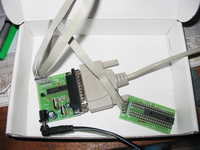
Here's the whole system in action.
Another example. This shows a PIC18F452.